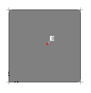
Shell, Plate ve Membran
In SAP2000, there are five options to design slab; shell-thin, shell-thick, plate-thin, plate-thick and membrane.
In membrane systems; only in-plane forces and moments perpendicular to the plane are formed.
In plate systems; only bending moments and shear forces perpendicular to the plane are formed.
In shell systems; it is a combination of membran and plate system behaviours. All forces and moments are formed.
There are various assumptions for Thick and Thin systems. These are thick and thin (Kirchoff) plate assumptions.
PLATE THIN ;assumptions:
- The material is homogeneous, isotropic and linear elastic, Hooke's law apply.
- The plate is initially flat.
- It remains small compared to other dimensions of the length h of the plate. The smallest horizontal dimension of the plate must be at least ten times larger.
- The transverse bends remain small compared to the plate thickness w(x, y). The maximum deflection of one tenth of the thickness is considered as the limit case of the small-deflection theory.
- The curve of the bent middle surface is small compared to the whole.
- Shear deformations usually are neglected. This assumption is Bernoulli's hypothesis for beams for plates.
- The normal stress σz is negligible.
σy = Eεy + νσx
σx = [E/(1-ν2)] (εx + νεy )
σy = [E/(1-ν2)] (εy + νεx )
τxy =τyx = Gγxy
PLATE THICK :
In thick plate theory, neglected shear stresses in thin plate are also taken into consideration. The problem increases from two to three dimensions.
| σx | τxy | τxz | |||
|---|---|---|---|---|---|
| T = | τyx | σy | τyz | ||
| τzx | τzy | σz |
Membran :
Membranes are very thin plates without bending resistance. The shell is assumed to be very thin and expressed in the middle surface. In this case the shell thickness and vertical displacement are zero. In the case of membrane stress, only the cross-sectional effects of Nx, Ny, Nxy remain.
| σx | τxy | τxz | |||
|---|---|---|---|---|---|
| T = | τyx | σy | τyz | ||
| τzx | τzy | σz |
| σx | τxy | τxz | |||
|---|---|---|---|---|---|
| T = | τyx | σy | τyz | ||
| 0 | 0 | 0 |
| σx | τxy | 0 | |||
|---|---|---|---|---|---|
| T = | τyx | σy | 0 | ||
| 0 | 0 | 0 |
In accordance with the aforementioned statements, it is recommended to design the slabs as membranes in reinforced concrete structures. Thus, the slabs are operated as a rigid diaphragm, there is no moment in the slabs and the resulting Nx, Ny forces are transferred to the supporting element.
It is recommended to be designed as shell or plate for elements such as retaining walls and shear walls. The design of the slab element as shell or plate does not cause a difference on the stresses that occur. The differences between the stresses to occur will be considerable in the elements such as dome. It is recommended to use shell option in dome-like structures.
While the element is modeled with both the shell and the plate, the element is meshed at regular intervals to provide more accurate results.
However, membrane elements will be transfer the forces ,will be formed, to the support elements. That's why the system will collapse in case mesh since nodes do not have elements to transfer the forces to be formed.
In the below, five cases in SAP2000 are modelled and analysed. As can be seen from the figures, moment was not formed in membrane element. Moment and stress patterns and values of Shell-thin and Plate-thin elements and Shell-thick and Plate-thick elements are the same.
Slab thickness of each element was selected 15 cm. Slab dimensions were chosen 2 meters for to apply thin (kirchoff) plate theory in Thin elements. Slab dimensions were chosen 1 meter for to apply thick plate theory in Thick elements.
Each Shell and Plate element is divided into pieces at 25 cm intervals.
 Membran
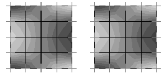 Plate-Thick and Shell-Thick
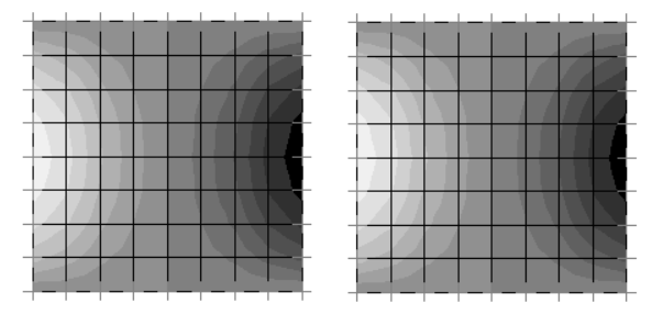 Plane-Thin and Shell-Thin